Normal Map
Turns a light-and-dark picture into a surface direction map for 3D materials.
The Normal Map node reads a picture as a height map — light means high, dark means low — and works out which way the surface faces at every point. The result is the purple-blue picture that 3D materials use to fake fine surface detail.

- One picture in, one out
- The output is data for a material, not something to look at
- It looks mostly lavender — that is correct
- Found under Texture in the add-operator list
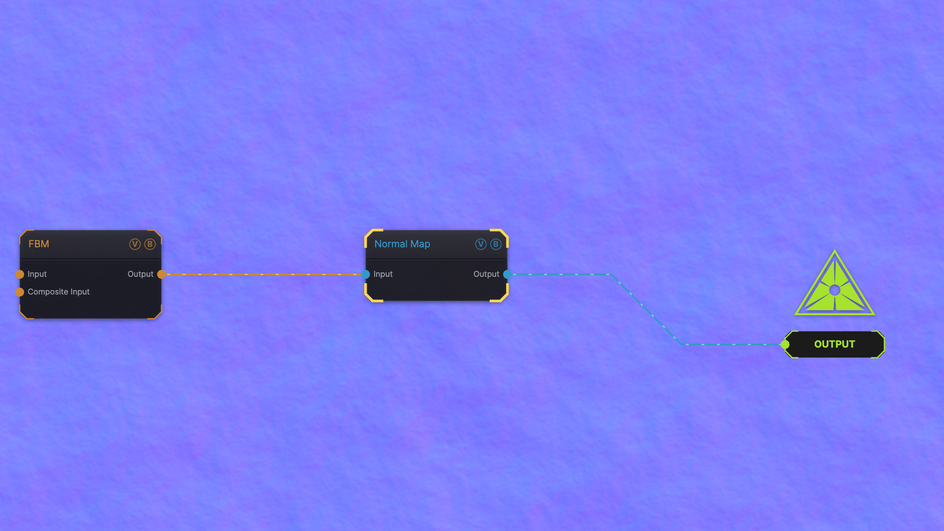
The image on the right is the example patch itself — drag and drop it onto the app (or load it with File → Load) to open the full graph.
Inputs and outputs
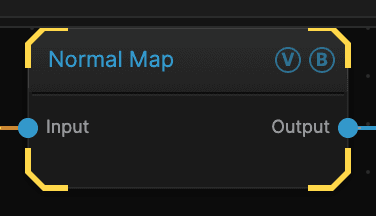
| Port | Type | Purpose |
|---|---|---|
| Input | Texture | The picture to work on |
| Output | Texture | The result |
Wire the output into a 3D Material node's Normal slot. Feeding it to the Output node shows you the raw data, which is useful for checking the strength but is not a picture you would show.
Parameters
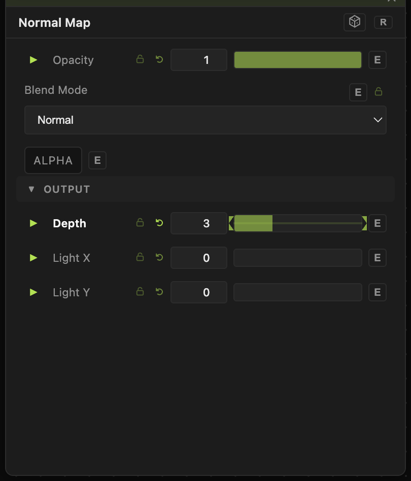
Opacity, Blend Mode, ALPHA — the standard operator header, on every operator. See Parameters and Controls.
- Depth (0–10, default 1) — how strong the fake relief is. Higher means steeper, more pronounced bumps.
- Light X and Light Y (−1 to 1, default 0) — bias the result toward one direction.
Troubleshooting
The 3D surface still looks flat — raise Depth, and check the material actually has the map wired into its Normal slot.