Trace Network
Dense interconnected circuit traces with animated routing, junction pads, and components.
The Trace Network node grows a web of right-angled circuit traces between cells, complete with junction pads and connection points. The traces animate — bright leading tracers draw each line before it fades — for a live, routing-in-progress look.
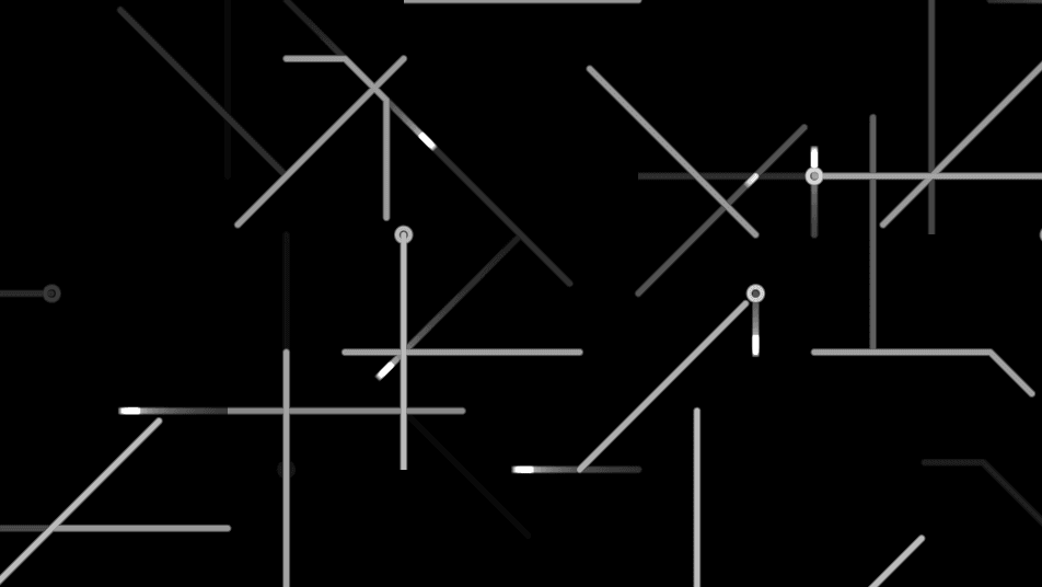
- One texture output; two optional texture inputs (domain warp and composite)
- Controls for cell grid, trace density, routing, and the animated tracers
- Found in the node graph under Generators as Trace Network
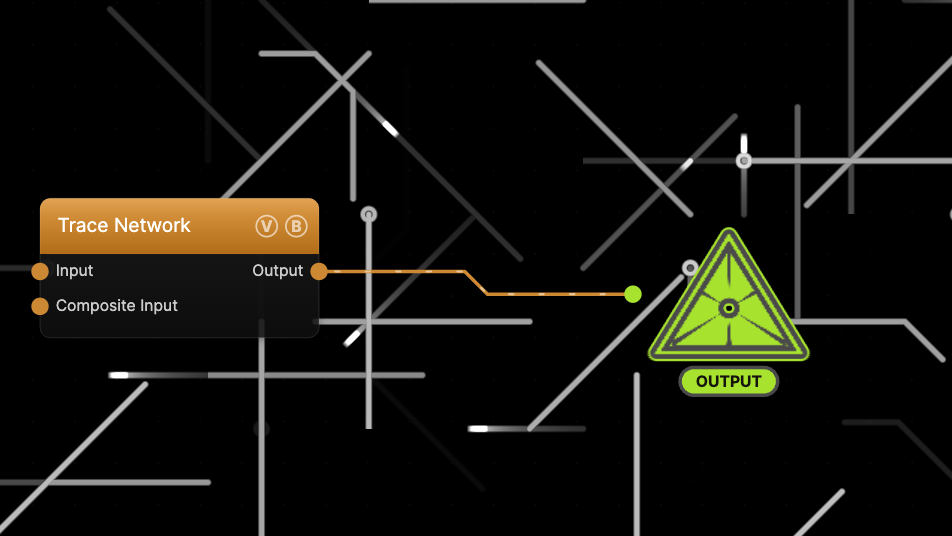
The image on the right is the example patch itself — drag and drop it onto the app (or load it with File → Load) to open the full graph. It sets a denser grid than the defaults so the network reads clearly.
Inputs and outputs
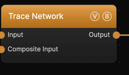
| Port | Type | Purpose |
|---|---|---|
| Displace | Texture | Domain warp: the red and green channels push the sample coordinates by Displace Amount |
| Composite Input | Texture | Composited under the output with Composite Mode and Composite Mix, which appear once the port is wired |
| Output | Texture | The grayscale trace network on black |
A black (or disconnected) Input produces no warp; the warp strength scales with Scale.
Parameters
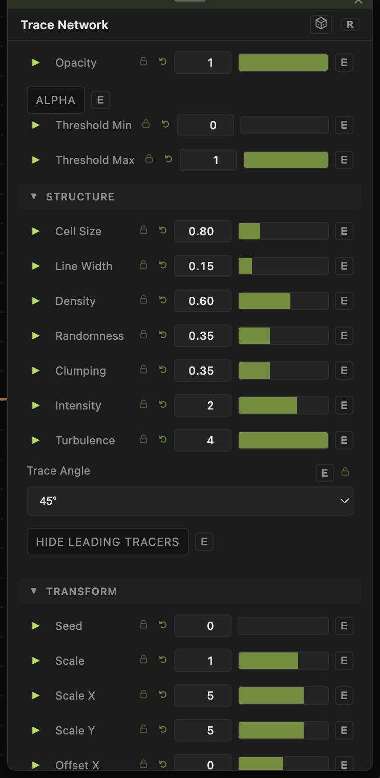
Opacity, Blend Mode, ALPHA, Invert Alpha, Threshold Min / Threshold Max — the standard operator header; see Perlin Noise for details.
Structure
- Cell Size (0.1–3, default 0.8) — the routing-grid cell size; smaller values mean shorter, denser traces.
- Line Width (0–1, default 0.15) — thickness of the traces.
- Density (0.05–1, default 0.6) — the fraction of cells that spawn a trace.
- Randomness (0–1, default 0.35) — variation in routing direction and cell choice.
- Clumping (0–1, default 0.35) — biases traces to gather into busy regions.
- Intensity (0.1–3, default 2) — brightness of the traces.
- Turbulence (1–4, default 4) — how much the routing bends away from straight runs.
- Lifetime (0–1, default 0.25) — how long each trace persists before fading. Higher values keep more of the network visible at once.
- Trace Angle — routing angle: 45° for diagonal runs or 90° for strict right angles.
- Hide Leading Tracers — when on, hides the bright leading spark and the seed pads, leaving just the static trace lines.
Transform
- Seed (0–99999) and the shared Scale / Offset / Rotation block.
Dynamics
- Speed (0–5, default 1) — rate at which traces draw and fade, compounding with the global animation speed. 0 freezes the network.
Every slider has a per-parameter animation bar, so any of these can be animated, audio-driven, or MIDI-mapped — see Parameters and Controls.
Troubleshooting
Only a few short traces show — the default grid is sparse; lower Cell Size and raise Density and Lifetime so more of the network is visible at once (the example patch does this).
Traces flicker in and out — that is the draw-and-fade animation driven by Lifetime and Speed. Raise Lifetime, or turn on Hide Leading Tracers for a static wireframe.
Network doesn't move — the node's Speed is 0, or global animation is paused in the transport bar.